- View sweeps by clicking on an Analysis
Graph data point - Impose single and averaged sweeps
- Quarantine bad sweeps in reanalysis
- PopSpike Area, Amplitude & Latency
- Three types of Slope measurement
- Analyze all EPSPs in a sweep
- Special analyses of trains Rs measurement from unfiltered trace
- Convert WinLTP data files to ABF files
- Reanalysis of ABF, IBW and WCP files
| Single-Line Automated Perfusion for Patch-Clamping |
In the multi-slice with pre-flushing section we have discussed changing perfusion solutions between sweeps during extracellularly recorded multi-slice experiments, and using pre-flush and other techniques to reduce the amount of stale, unoxygenated solution delivered to the slice during solution changes. However, automated perfusion of single cell patch-clamp recording and has a different set of problems. First, single cell patch-clamp experiments use a HEPES or similar type buffer rather than a 95% O2 / 5% CO2 bicarbonate buffer, so there is not the concern about stale, unoxygenated altered pH solution in the lines. The dead volume between the reservoir and the manifold is not a crucial concern, and pre-flushing the perfusion lines is not necessary. However, in these experiments, perfusion solutions have to be changed very quickly – sometimes within a millisecond, and so automated perfusion has to be able to be quickly changed both during as well as between sweeps.
There are two methods of automated perfusion control of single cell patch-clamp experiments. The first method is using a single-line perfusion between the manifold and the end of the pipette near the cell, and solution application lasting 10’s of milliseconds to seconds. The second method is to use a stepper to move two or three perfusion tubes, and solution applications can be as short as 1 ms.
In the single-line perfusion system (which is similar to the Slice Standard System, Fig. 3.2A), changing perfusion solutions between sweeps is controlled by the Perfuse event in the Protocol Builder, and fast perfusion change during the sweep is controlled by changing either digital or analog output during the sweep.
An example of single-line fast perfusion changes during and between sweeps is shown in Fig. 3.4. This is for controlling an 8 channel perfusion controller using AnalogOut1 and to for applying 4 different agonists and 4 different antagonists when the antagonist does not rapidly unbind. The four different agonist concentrations are applied during the four different sweeps. The protocol in the Protocol Builder (left panel) starts with the Fast0 Perfuse event in the Protocol Builder causing Ch1 Antagonist 1 to be perfused. After a delay, Ch5 Agonist 1 is applied for 1 second during the P0sweep. Then shortly thereafter Ch6 Agonist 2 is applied during a P1sweep, Ch7 Agonist 3 is applied during a T0sweep, and Ch8 Agonist 4 is applied during a T1sweep. Then the perfusion solution is changed to Ch2 Antagonist 2, and application of the 4 agonist solutions is repeated, and this is repeated for Ch3 Antagonist 3 perfusion, and finally for Ch4 Antagonist 4 perfusion. During the first and third epochs, Step0 and Step2, a -1 in the Amplitude (V) field (red rectangles) causes the current perfusion solution set by the Fast0 Perfuse event in the Protocol Builder to be maintained in that part of the sweep. During the Step1 epoch, a voltage from 1 to 8 in the Amplitude (V) field (black rectangle) changes the perfusion to Chs 1 to 8.
For more information see Section 10.3 in the on-line WinLTP Manual.
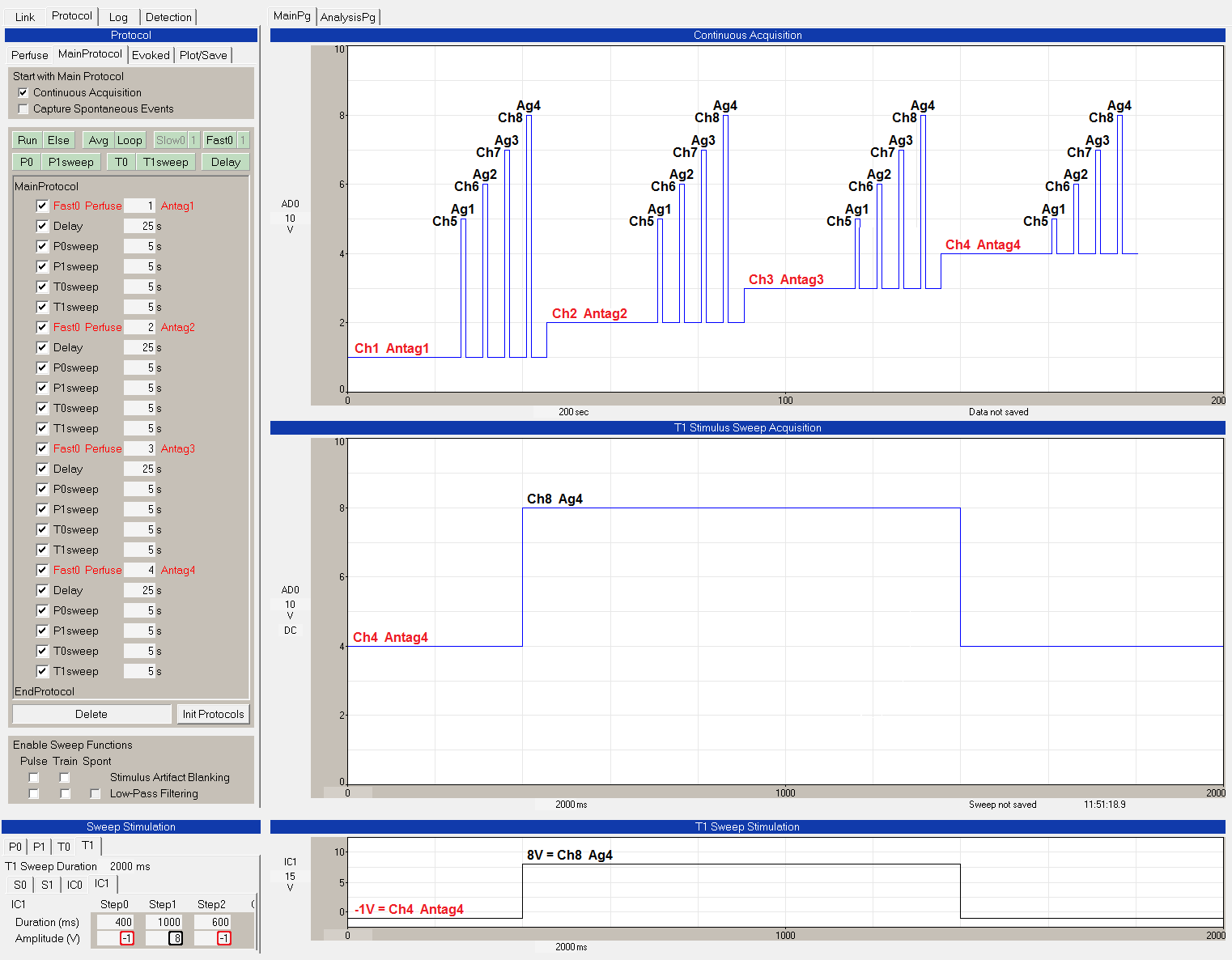 |
| Fig. 3.4. Single cell, single-line fast perfusion changes during and between sweeps - applying 4 different agonists and 4 different antagonists when the antagonist does not rapidly unbind. The Fast0 Perfuse events (shown in red in the Protocol Builder panel on the left) set the on-going perfusion to Ch1 Antag1, Ch2 Antag2, Ch3 Antag3 and Ch4 Antag4. Four different concentrations of agonist are applied during the 4 different sweeps. During the Step1 epoch in the T1sweep (bottom panels), a voltage of 8 in the Amplitude (V) field (black rectangle) changes the perfusion to Ch 8 or Agonist 4. |
Using Protocol Linking to Link Single-Line Perfusion Protocols
WinLTP currently can output four different sweep stimulations (P0, P1, T0 and T1) from one protocol file. When the antagonist is tightly bound, this means you could deliver 4 agonist concentrations and up to 12 different antagonist concentrations (for up to 16 channels) in one protocol file. However, when the antagonist is loosely bound and the agonist solutions must also contain an antagonist, you could deliver only 1 antagonist concentration and 4 agonist concentrations (with that one antagonist concentration) in one protocol file. To test more agonist and antagonist concentrations, you could use Protocol Linking to automatically load a new protocol file and run it ad infinitum.
For more information, see the webpage on Protocol Linking, and Chapter 9 and Section 10.3.2 in the on-line WinLTP Manual.