- View sweeps by clicking on an Analysis
Graph data point - Impose single and averaged sweeps
- Quarantine bad sweeps in reanalysis
- PopSpike Area, Amplitude & Latency
- Three types of Slope measurement
- Analyze all EPSPs in a sweep
- Special analyses of trains Rs measurement from unfiltered trace
- Convert WinLTP data files to ABF files
- Reanalysis of ABF, IBW and WCP files
|
Dual- and Triple-Line Automated Perfusion
with Stepper Control for Patch-Clamping |
Single-line automated perfusion control for patch-clamp experiments is used to produce solution applications in the tens of milliseconds and up timeframe. In contrast, dual- and triple line perfusion using a stepper to control which tube bathes the cell can produce perfusion applications as short as a millisecond in duration.
WinLTP’s control of a triple-line/stepper
perfusion system is shown in Fig. 3.5. Slow0 and Fast1 perfusion
each controls one perfusion controller, each of which in turn
usually controls 4 to 16 valves. Slow0 and Fast1 usually output
agonist or agonist + antagonist solutions from Tube0 and Tube2,
respectively. The Slow1 perfusion controls another perfusion
controller which in turn controls 4 to 16 valves. Slow1 usually
outputs antagonist only solutions from Tube1. The Slow0, Slow1 and
Fast1 perfusion changes solutions between sweeps. The Fast0
perfusion controls the stepper which quickly moves the antagonist
only Tube1 to either agonist (+ antagonist) Tube0 or Tube2 during
the sweep. If the stepper is a fast piezo device, solution
applications from Tube0 or Tube2 can be as quick as one millisecond
in duration. The only difference between dual- and
triple-line/stepper perfusion is that dual-line perfusion does not
use Fast1 perfusion or Tube2.
For triple-line/stepper perfusion, WinLTP can easily control 16
valves and solutions by Slow0, Fast1 and Slow1 each, so WinLTP can
easily control 16 concentrations of antagonist solutions ( Slow1)
and 32 concentrations of agonist (+ antagonist) solutions (Slow0 and
Fast1), or a total of 48 solutions. The problem is
more cost of the valves and controllers, and the difficulty in
setting up that many perfusion lines, rather than with limitations
in WinLTP.
Fig. 3.6 shows a protocol involving three perfusion lines and
side-by-side tubes, Tube0, Tube1 and Tube2, controlled by Slow0,
Slow1 and Fast1 perfusion, respectively. Fast0 controls a stepper to
switch from Tube1 to Tube0, or Tube1 to Tube2. The Slow0 Perfuse,
Slow1 Perfuse and Fast1 Perfuse events in the Protocol Builder
(upper left) show when the Slow0/Tube0, Slow1/Tube1 and Fast1/Tube2
solutions are changed.
For more information see Section 10.4 in the on-line WinLTP Manual.
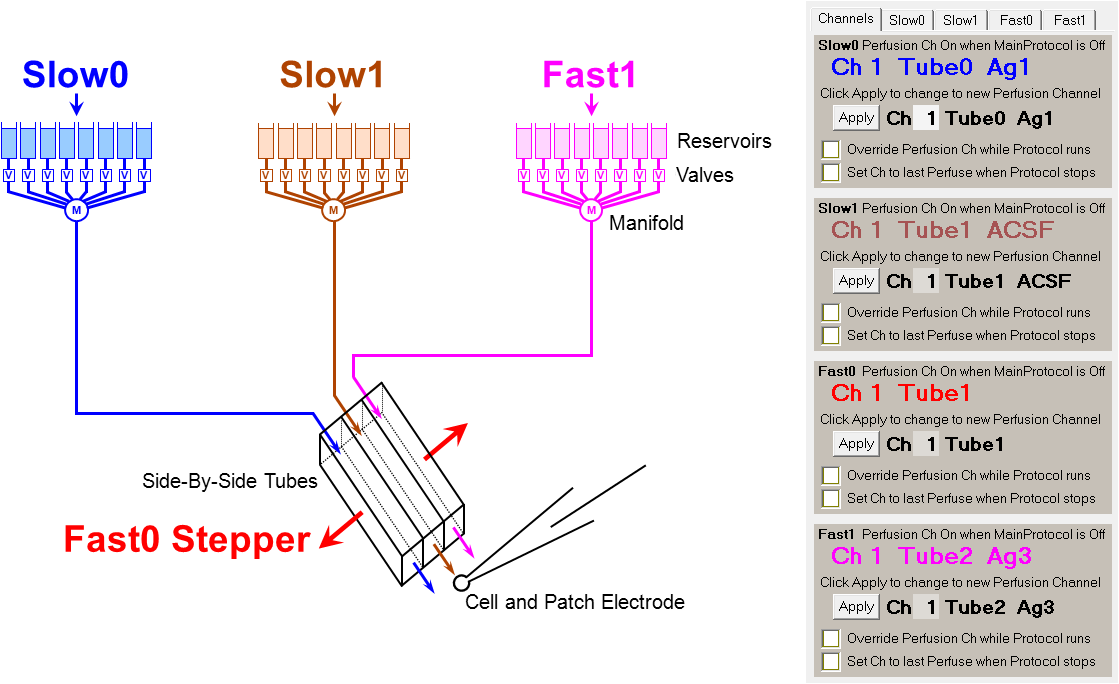 |
| Fig. 3.5. WinLTP control of triple-line perfusion using a Stepper. (a) Slow0, Slow1 and Fast1 Perfusion control three valve controllers with up to 16 solutions per controller, and the Fast0 Perfusion controls the stepper which controls whether the solution from Tube0 (blue), Tube1 (brown) or Tube2 (fuchsia) bathes the cell. The Fast0 Stepper therefore controls whether antagonist (Slow1) or agonist (Slow0 or Fast1) is applied. (b) The panel showing manual control of the color coded Slow0, Slow1, Fast0, and Fast1 perfusion channels. |
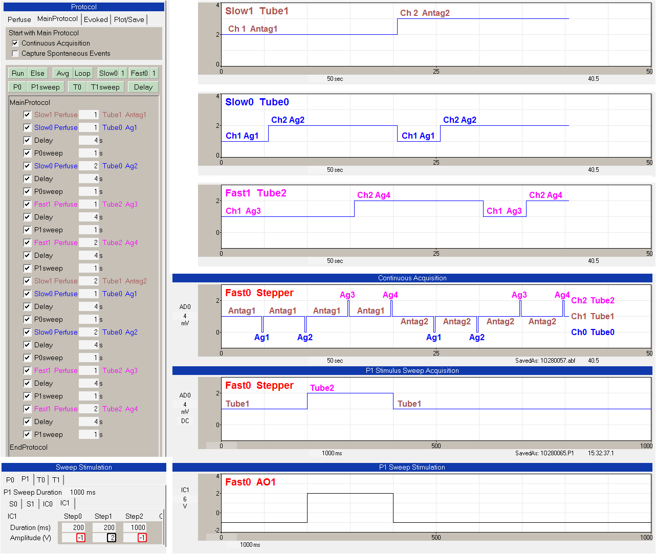 |
| FIg. 3.6. Triple-line automated perfusion with stepper control. The Slow0 Perfuse, Slow1 Perfuse and Fast1 Perfuse events in the Protocol Builder (upper left) show when the Slow0/Tube0, Slow1/Tube1 and Fast1/Tube2 solutions are changed. The upper right panel shows the Slow1/Tube1 switch from Ch1 Antag1 to Ch2 Antag2. The next panel below shows the Slow0/Tube0 switch between Ch1 Ag1 and Ch2 Ag2. The next panel below that shows the Fast1/Tube2 switch between Ch1 Ag3 and Ch2 Ag4. The Fast0 Stepper ‘Continuous Acquisition’ and the Fast0 Stepper ‘P0 Stimulus Sweep Acquisition’ panels show recordings of the AnalogOut1 voltage momentarily changing from Ch1 Tube1 to Ch0 Tube0 or to Ch2 Tube2. The Sweep Stimulation bottom panels show the change of AnalogOut1 (IC1) voltage output during a P1sweep from 1V or Ch1 Tube1 to 2V or Ch2 Tube2. The -1V (red rectangles) means to take the current Fast0 output between sweeps, e.g. Ch1 Tube1. |